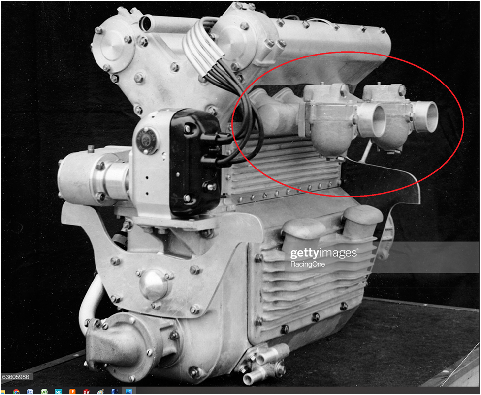
I like the look of the original two side draft carburetors to come as close to possible to the original as shown in the following photo:
However, I have never made a carb before and want to have a single carb set up for initial engine checkout. That is what I am going to fabricate here.
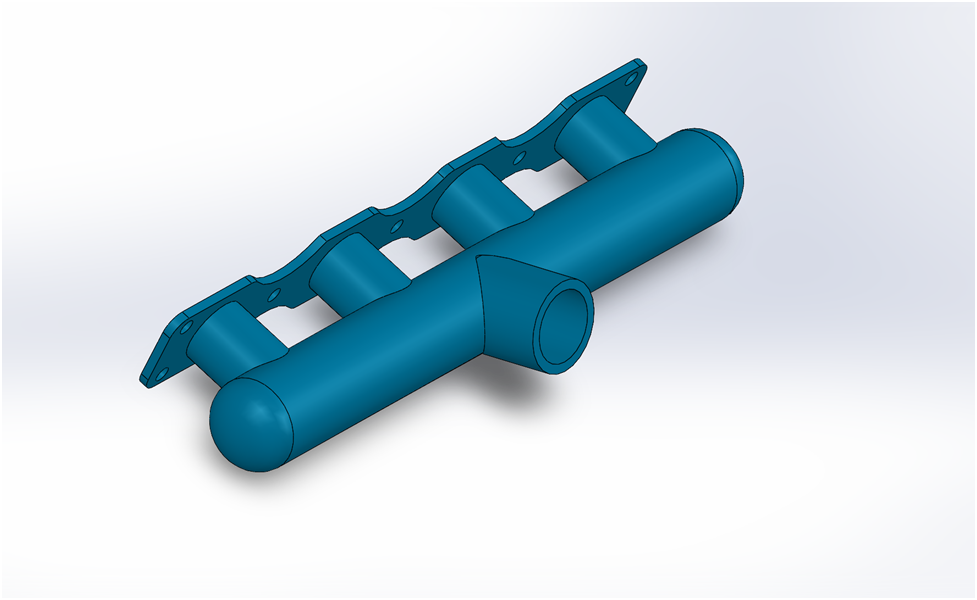
This is the design I have settled upon,
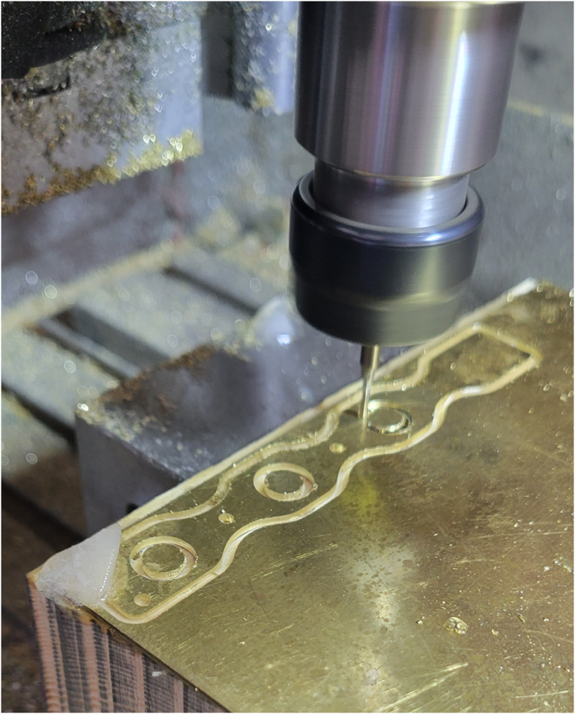
Below is the flange that mounts to the cylinder head being made on the CNC router. In the lower left hand corner is an ice chip that I used to keep the part cool during machining. My mister broke and I didn’t want to wait until another was delivered. When machining parts that use 5-minute epoxy as the hold down strategy, the parts needs to be kept cool, or the epoxy will soften or even give way and you end up with a ruined part at the least.
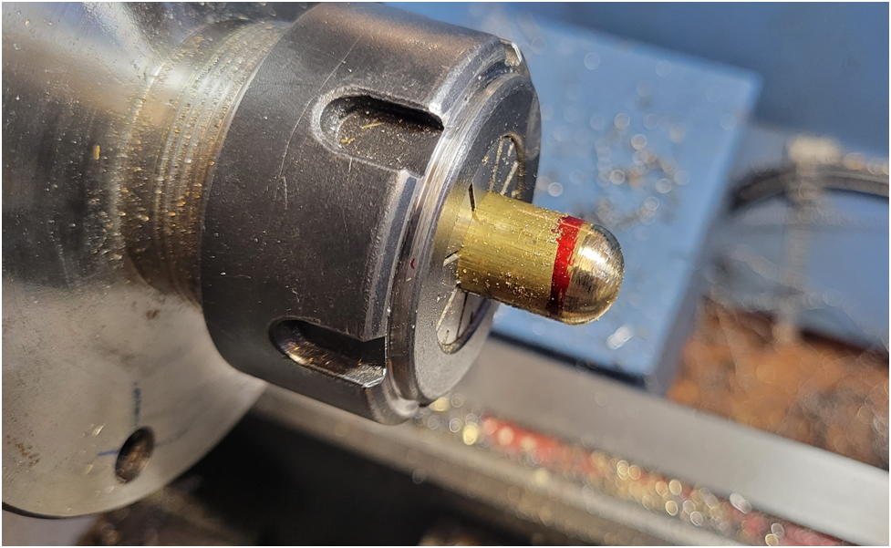
The end caps were machined from the solid. I took a 30 degree cut removing most of the material, then rounded the part with a file on the lathe.
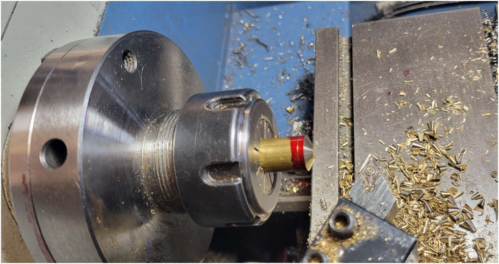
A step was then machined before parting off so the cap fits snuggly in the larger intake tube.
The large cross tube is .5″ in diameter, so I used a .5″ end mill to shape the intake runners and the carburetor mounting tube.
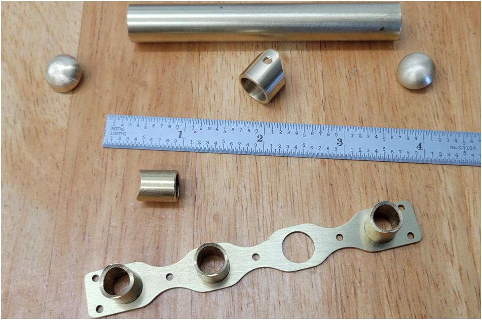
Below the parts are test fit. I decided to solder the assembly together first, then machine out the holes in the large cross tube. I think this will simplify the alignment of the parts during soldering.
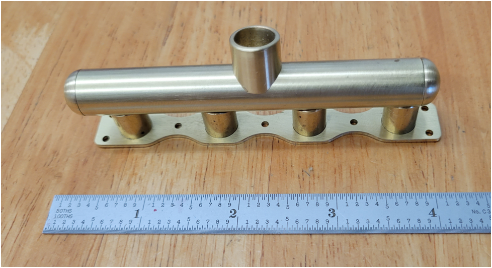
I am still formulating my soldering strategy. My thought is to solder the feeder tubes to the flange first, then the cross tube to the feeder tube and the carburetor tube last. Jewelers often use different formulations of silver solder that have slightly different melting temperatures that allow them to stage assembly of a piece. They use the higher temp solder first, the idea being they do not need to raise the temp of the piece as high for subsequent solder operations and not disturb previous work. The single roll of silver solder I have nearly broke the bank, so I am not going to be purchasing additional types.