Cylinder Head – Part 2
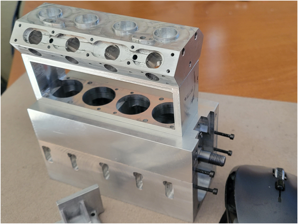
In this second installment describing the machining of the head, I show the steps to machine the two non-vertical/horizontal surfaces–the face the intake and exhaust manifolds mount to, and the face the cambox mounts to.
First I use the CNC router to machine the two bevel surfaces on each side. Why not use the router to complete the machining on these beveled sides? I couldn’t given the limitations of my little CNC router. The work piece is 4.125″ long and the vise on the CNC router can only open to 4″. My mill vise to larger, but I can’t use it on the CNC router because it is too tall and I don’t have enough Zed clearance. I reasoned that this part needs to be clamped from the ends since these are the only two vertical surfaces the vise can bear against. I looked at a couple of fixtures, but the rotational forces of clamping the part would result in an unreliable work holding situation.
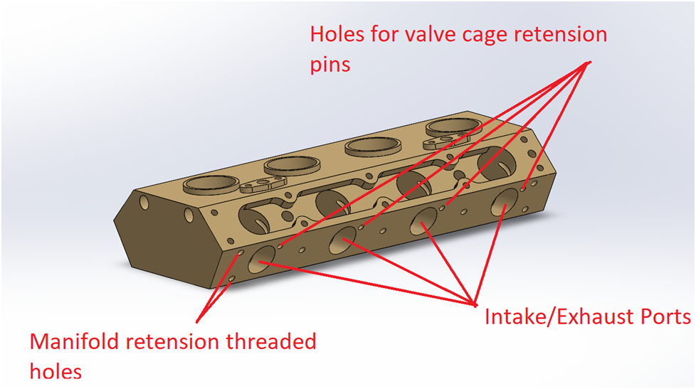
I can probably manual mill the features faster anyway. I decide to start with the simpler face first, the manifold mounting surfaces. The four port holes were machined in an earlier step, so already exist. There are only the 7 threaded holes for mounting the exhaust/intake manifolds and the 4 holes for the pins securing the valve cages. These are shown below.
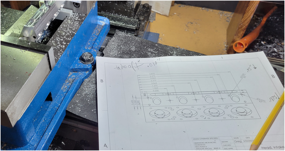
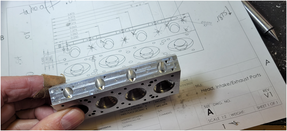
I have been creating the drawings for the parts as I build and machine them; this way I can find issues with the print. I find a couple of missing dimensions and hole callouts.
There is a fixture required to align the beveled surface I am working on. I decide to 3D print it. the fixture carries light loads during the milling operation and no clamping force. Designing and printing the fixture part is much quicker than using a piece of aluminum for a one off fixture.
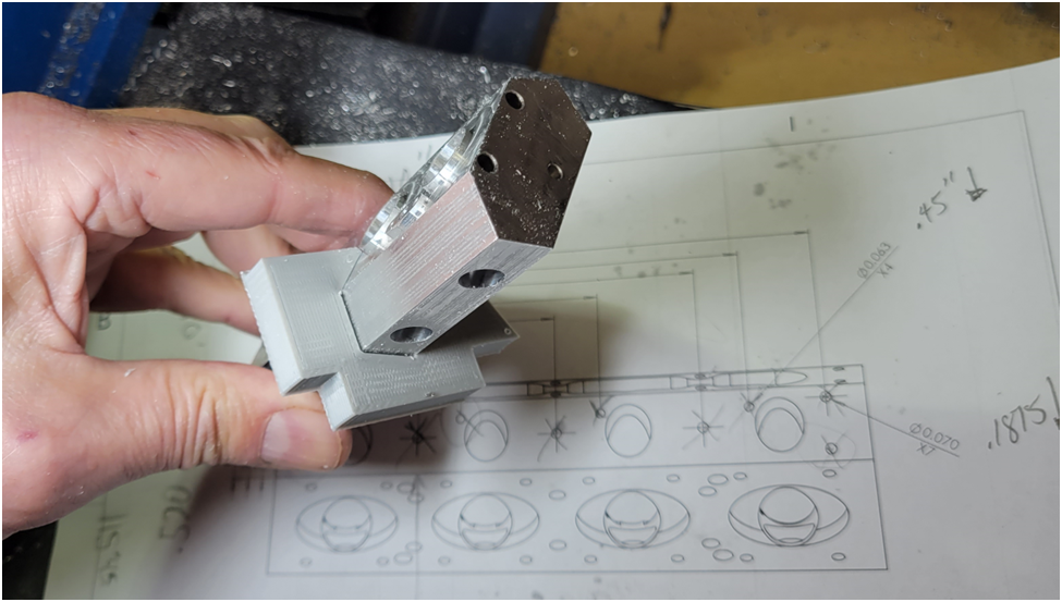
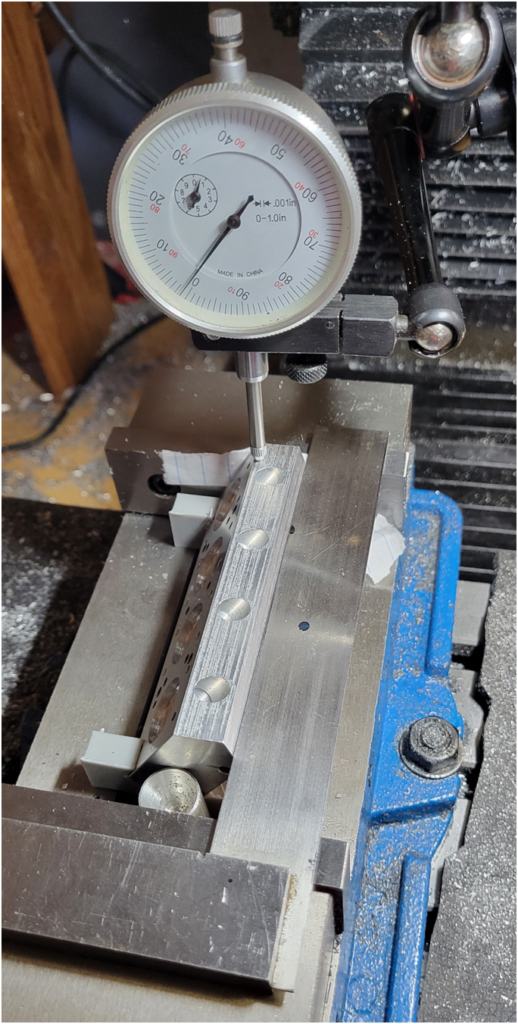
I do not rely on the plastic fixture alone. An indicator is used to verify and tweak the clamping to insure the surface is properly aligned with the mill table. You can see that a sheet of notebook paper was used as a shim to bring the part in perfect alignment. I use a square to confirm perpendicularity and an aluminum rod on the moveable vise jaw to insure only the primary face of the vise jaw is aligning the part.
As mentioned before the four large port holes were drilled in an earlier operation.
Once the part is secure in the vise and aligned to the mill, spot drilling, drilling and tapping the holes is routine.
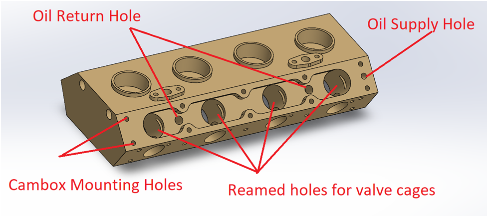
Machining the cambox face is more complex because in addition to drilling and tapping holes, I need to drill and ream the large holes for the valve cages, then machine the oil collection channel.
All of the machining on the head prior to today’s operations used the center of the part as the origin. This way any variation in the outside dimensions of the part will be spread evenly on all sides. If you look at the print in the picture above, you can see all the dimensions are referenced to edges. This could result in slight miss alignment as tolerances would be biased to one side. I realized this before I machined the Cambox surface and created the print using the center of the surface as the datum. I doesn’t really matter what is used as a datum as long as the machining operation on all of the faces use the same ones.
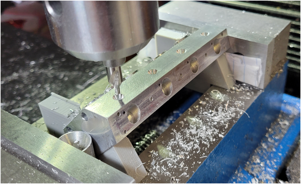
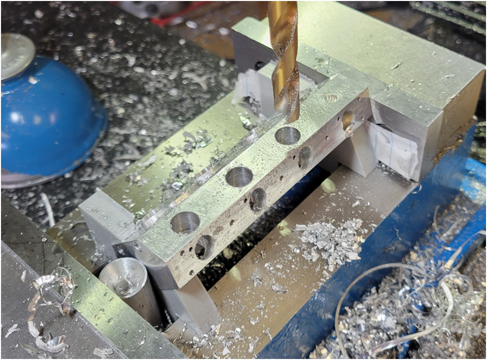
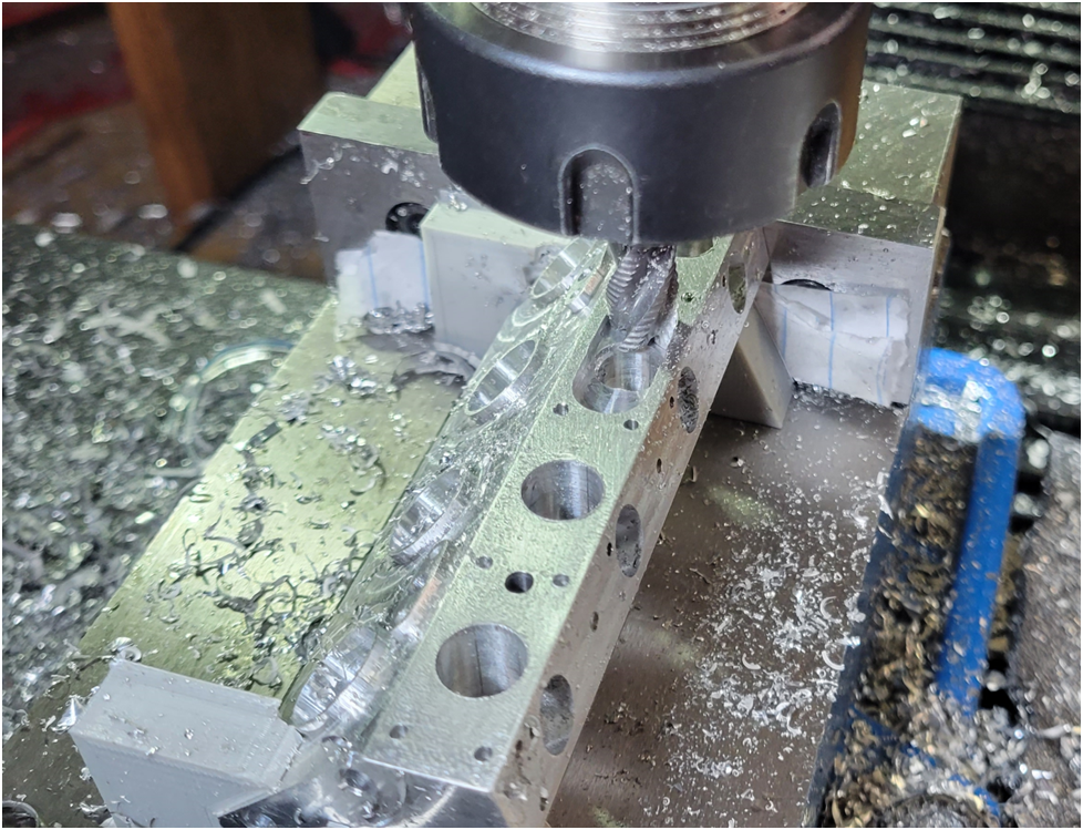
Below I spot drill the four holes for the valve cages.
Then drill them undersize.
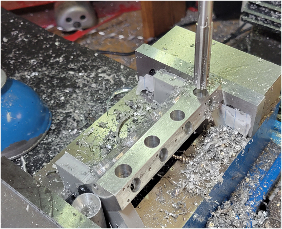
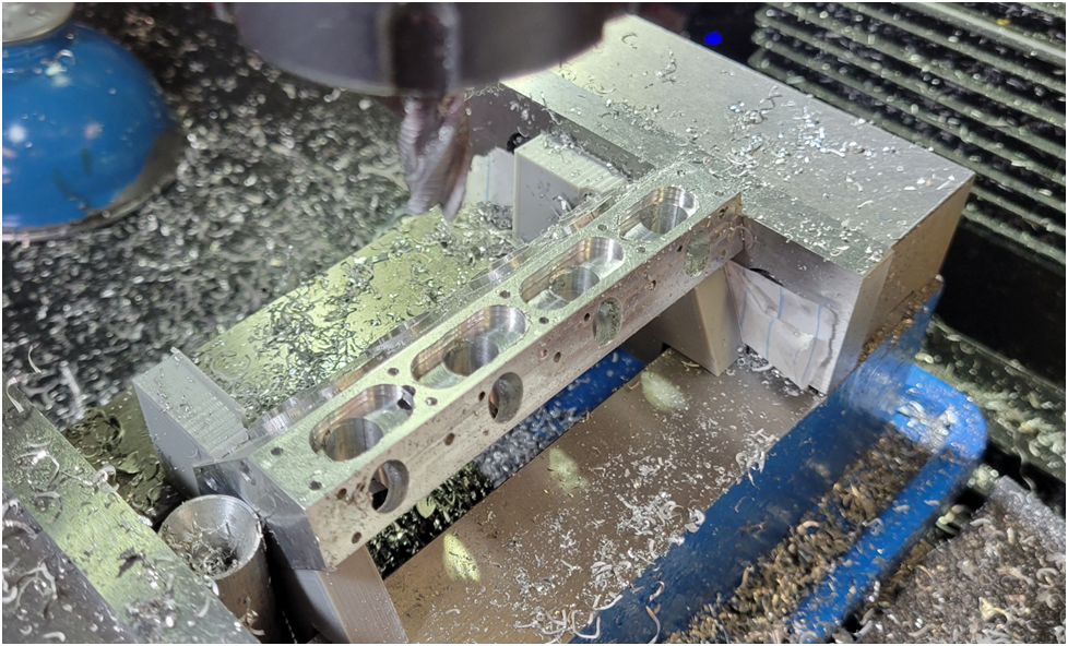
Then ream them to final size.
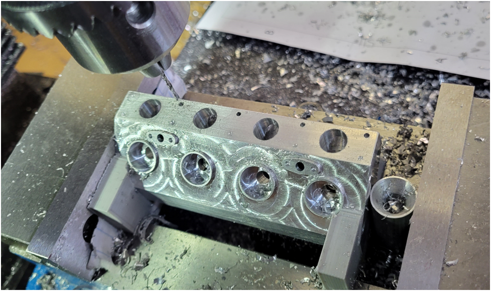
Then the threaded holes that secure the Cambox are spot drilled.
Drilled….
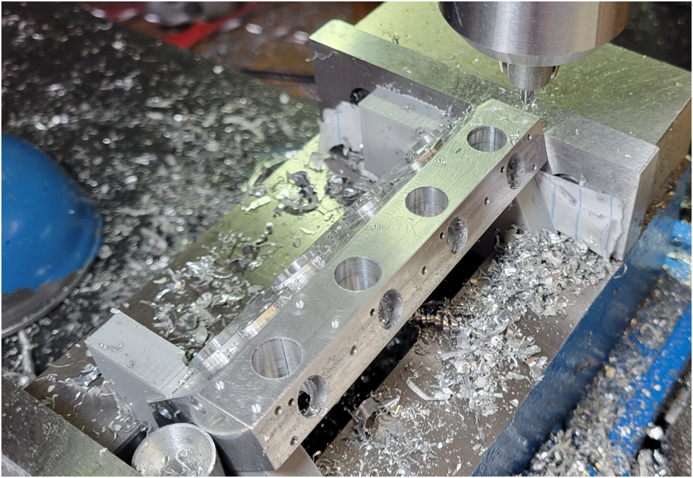
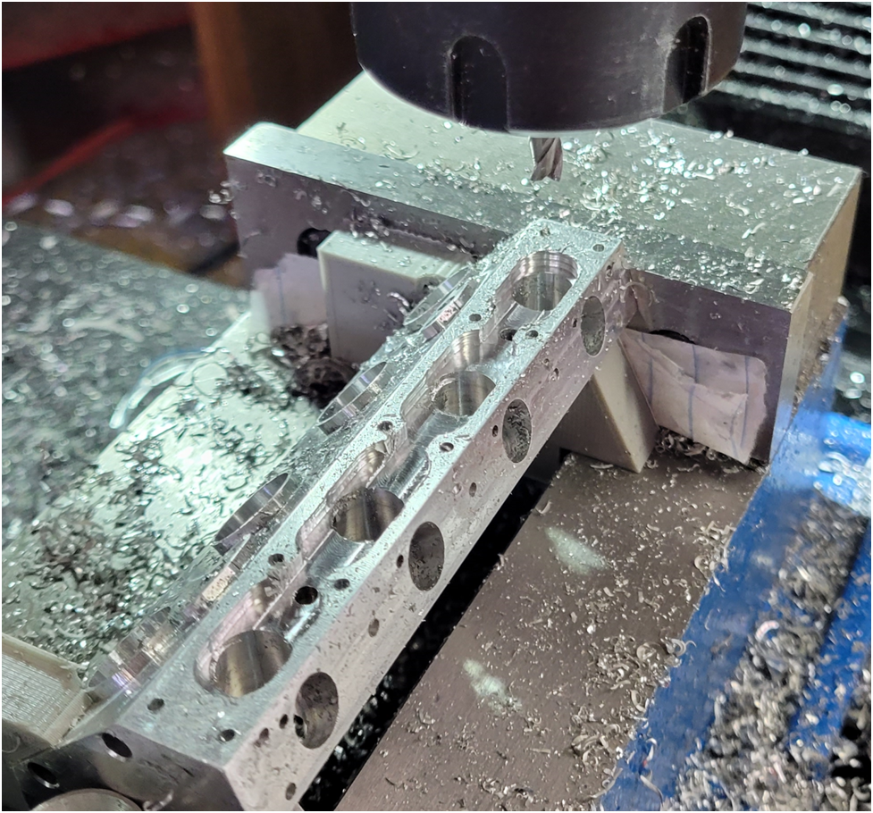
I use a 3/8″ roughing mill to machine the 3/8″ oil trough. I would prefer to have used a finishing end mill..but I don’t have one.
There is one final operation cutting the oil trough from end to end with a 3/16″ flat end mill.
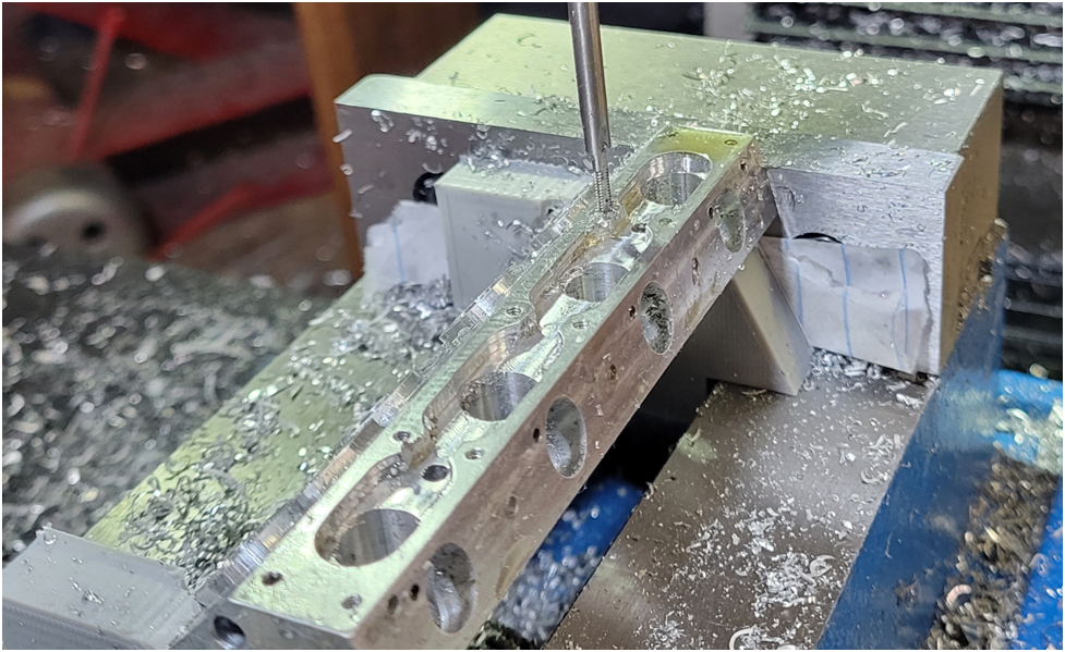
Finally I tap the threaded holes.
Then flip the part over and repeat for the other side.