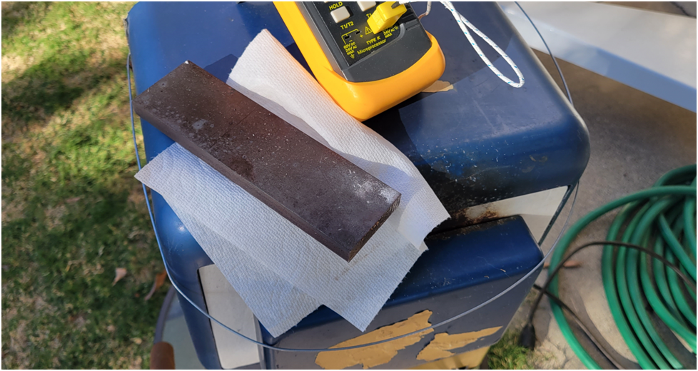
Time for the crankshaft. I start by stress relieving the steel in the heat treat oven. I heat it to 1150 degrees for two hours, then let it furnace cool over night.
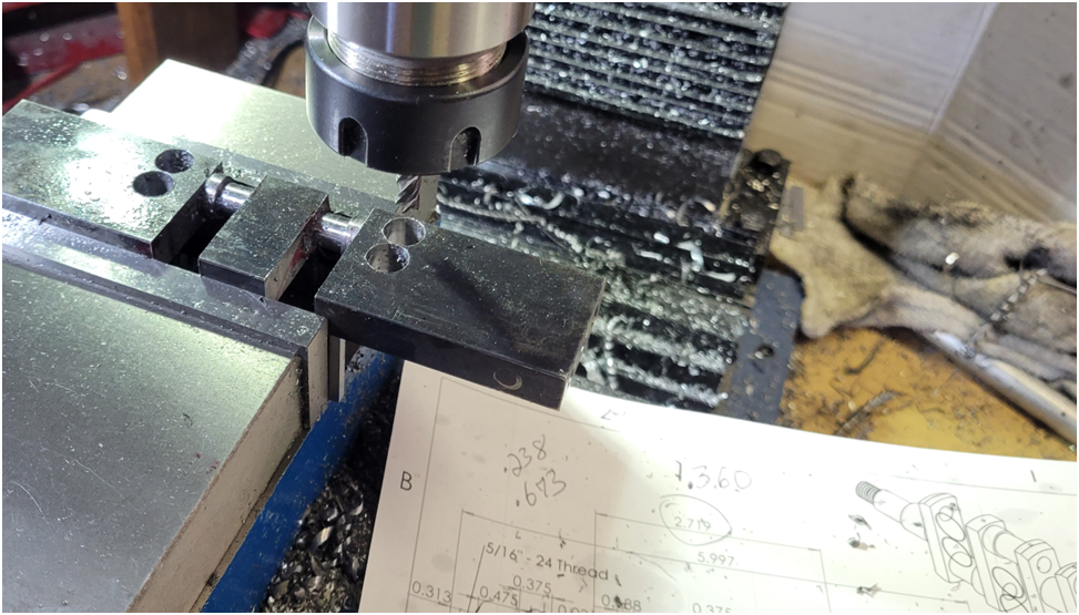
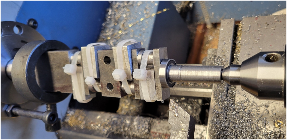
Notice in the image below that the compound has been replaced by a simple steel plate. The compound is the least rigid element in my bench top lathe and replacing it with this plate really helps the surface finish quality.
I remove most of the material on the mill, chain drilling and edge milling.
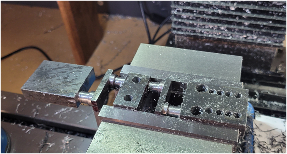
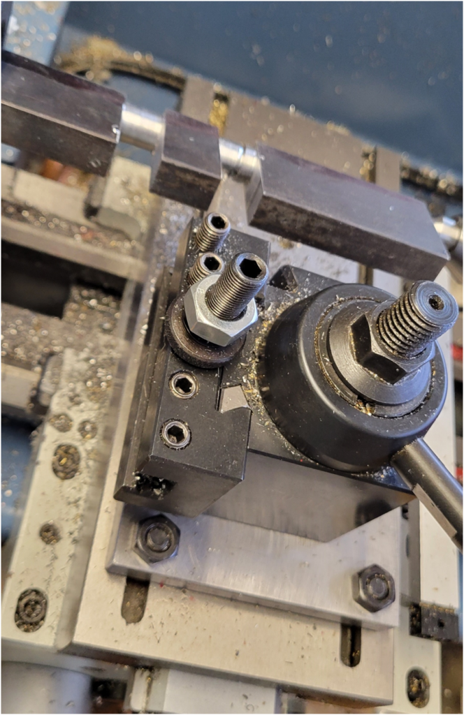
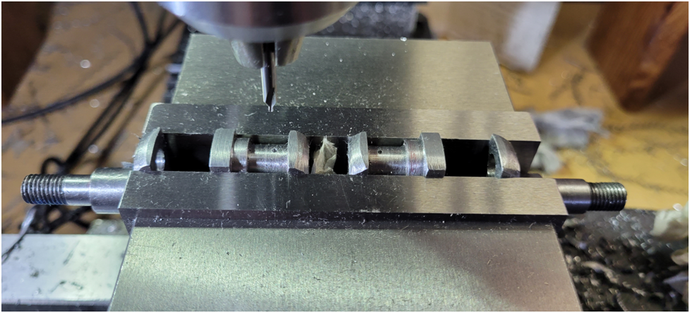
When machining a crankshaft by turning it on centers, there is a fair amount of force created by the tail stock holding the work piece between centers. This is important as it registers the crankshaft to the center and the live center for repeatable concentric machining. I have found that the spacers used to transfer this force between the crank webs must be accurately machined to be a close fit. Too tight and the spacers actually open up the webs while the crank is machined, which springs back once the spacers are removed. Too loose and the opposite happens–in either case the machined journals are not co-linear with each other. Also the interrupted cut can tweak the crankshaft as well, so small cuts are in order, even when roughing out the crankshaft. Each spacers shown below are custom machined on the mill for each crank web and are labeled so they can be returned to the correct position.
The ball bearing can be seen test fit on its main end journal.
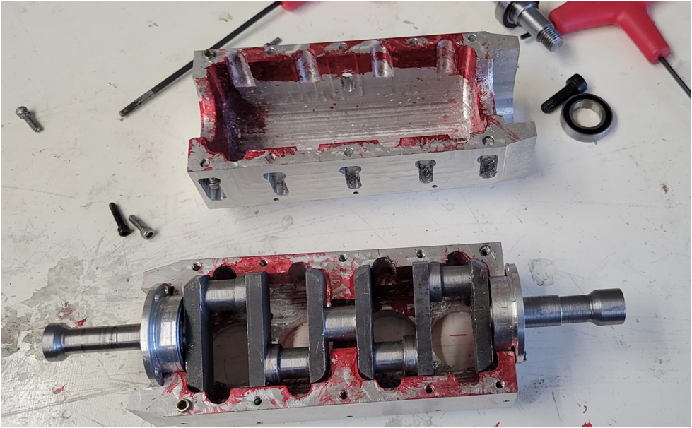
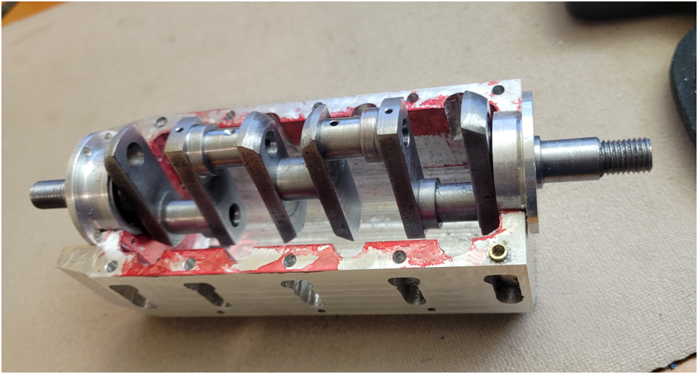
Below I am test fitting the crankshaft in the crankcase. The red Dykem is used to highlight any areas of interference.
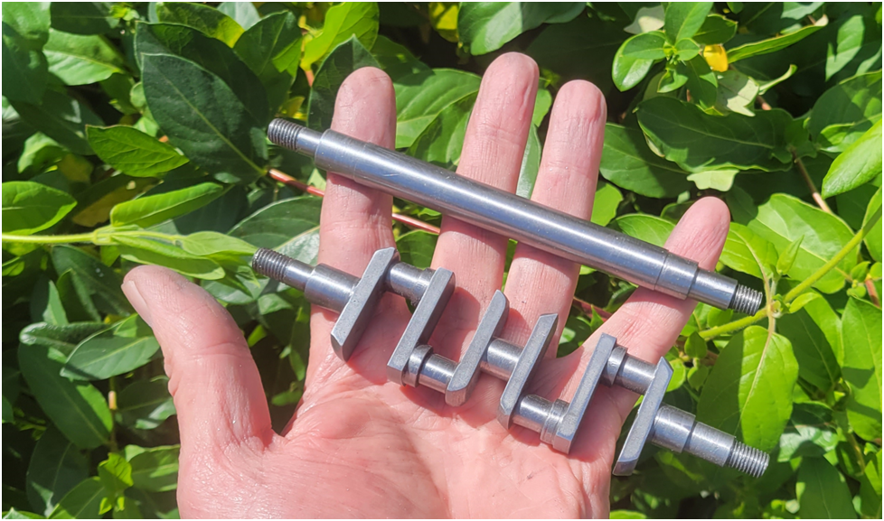
Below is the crankshaft with the major lathe work completed. It is next to the dummy crnakshaft I have been using up to this point.
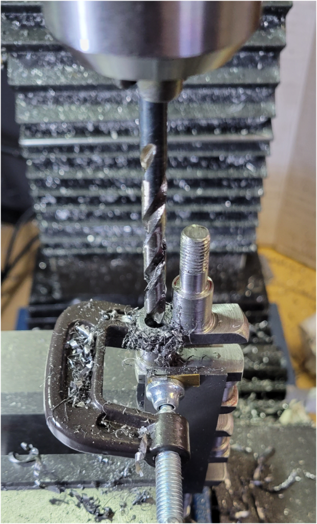
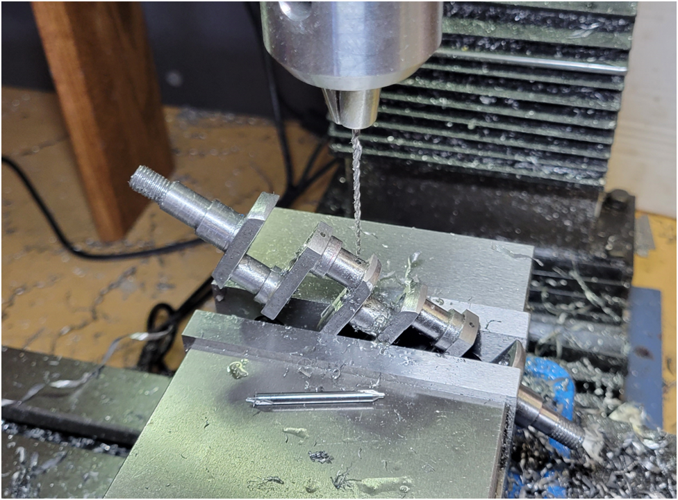
Below I am drilling the lightning holes through the center of the rod journals. These will have their ends caped and be part of the internal crankshaft oil system.
Below is a cross section of the crankshaft showing how oil is delivered to the connecting rod big ends. Oil is delivered to the center crankshaft main bushing under pressure. Note that the ends of the big lightning holes through the conrod big end journals will be capped at each end.
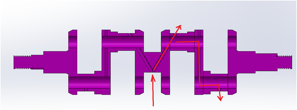
To drill the diagonal oil gallery, the starting position of the hole is spot drill with the crankshaft horizontal at the specified point.
Then the crankshaft is held at the specific angle and the beginning of the hole is spot drilled again. Finally, the hole is drilled through.
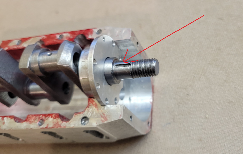
Then I machine the keyway for the timing gear placed at TDC for cylinder #1. Indicated by the red arrow.
The crankshaft is in good enough condition to allow the test assembly of the rest of the engine. At some point I will need to clean the crank really well and cap the large lightning holes.