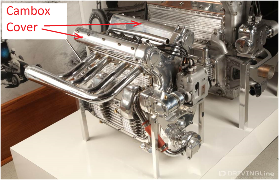
Cambox Covers
The cambox covers mount to the top of the camboxes and enclose the camshafts. They are often polished aluminum and are a distinctive feature of the Offenhauser engines.
In my scale they are sections of a .67″ tube–a non standard dimension. I thought of several approaches to their fabrication and settled on using .625″ OD tubing (.065″ wall) and stretch it to size using a form tool.
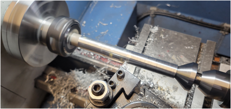
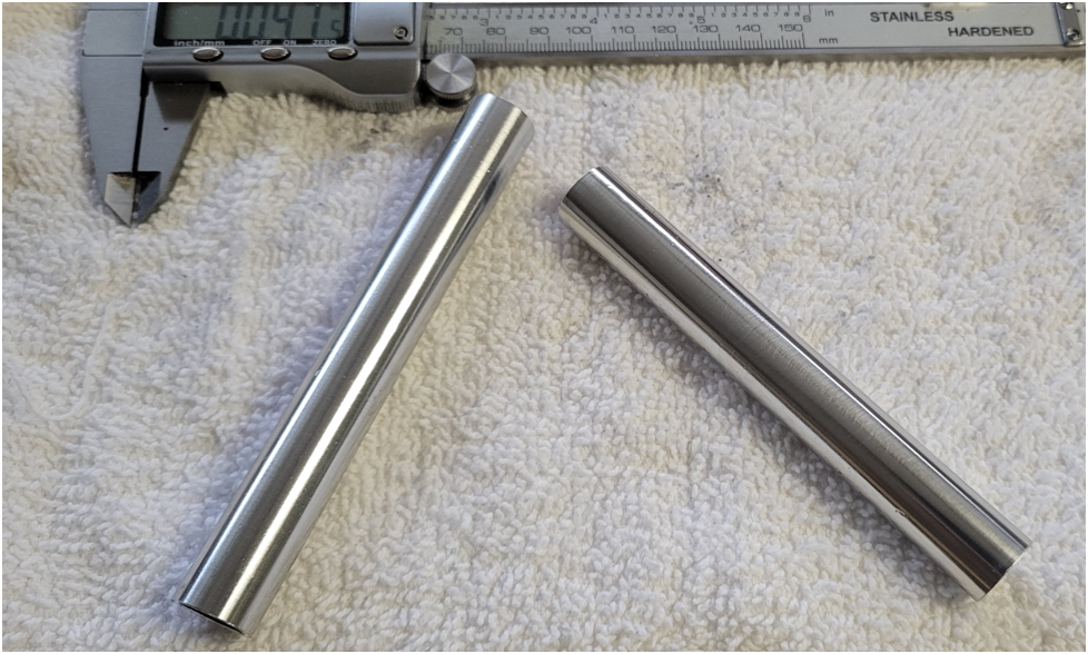
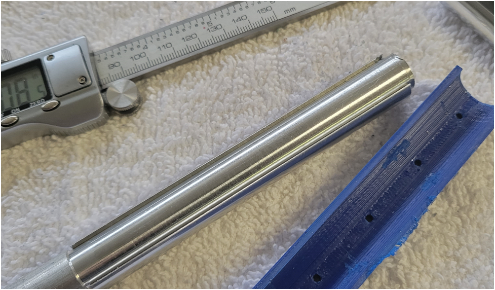
First I turn the outside of the tubing on the lathe and polish it, first with scotch brite, then fine steel wool and finally polishing compound on a rag.
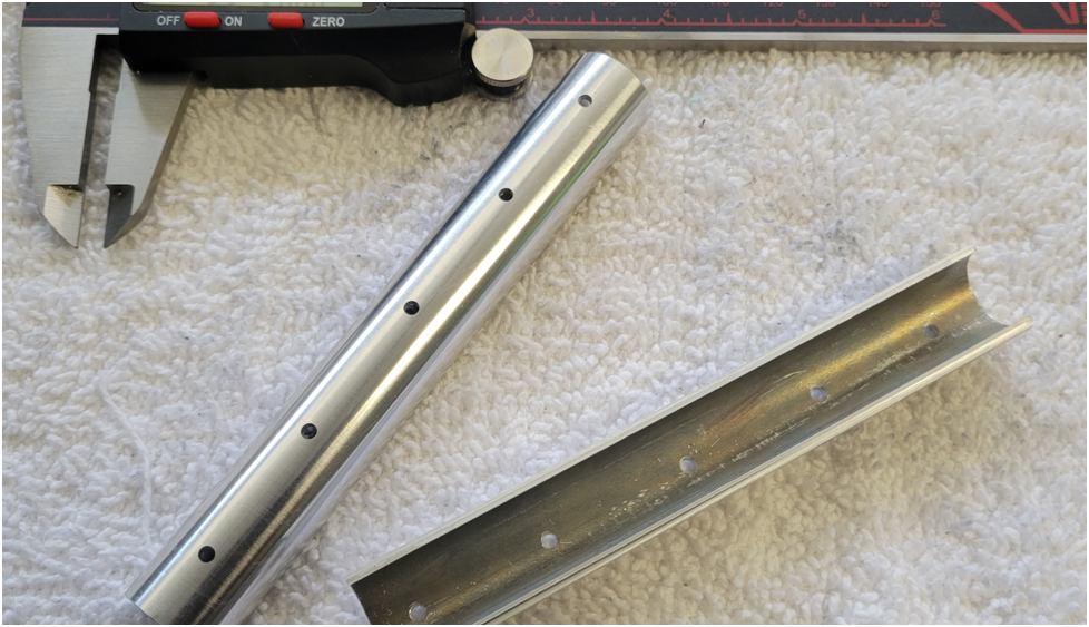
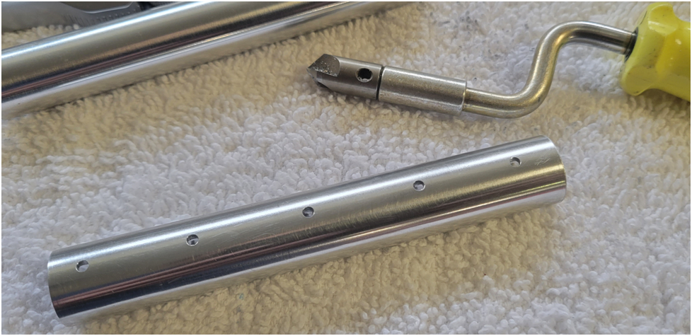
Below are the polished aluminum tubing work pieces. One I turned using a carbide insert and the other a HSS rounded tool. The HSS tool had the better finish.
Next I machine a .35″ slot in the tubing, leaving extra material.
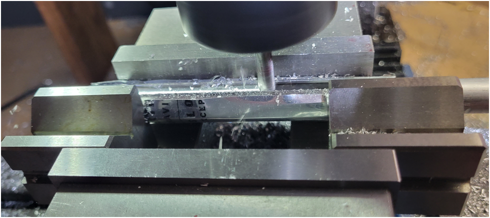
Below are the tube sections with the slot cut.
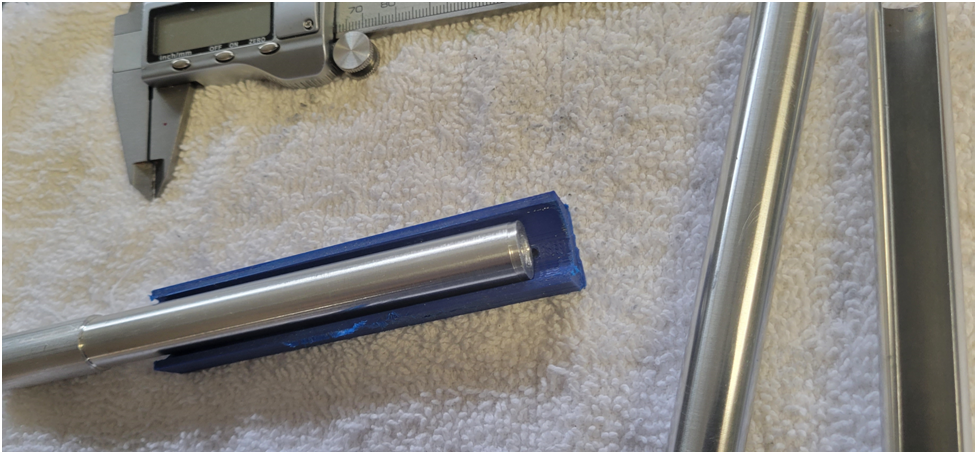
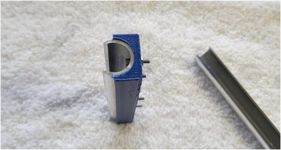
As mentioned above a form tool is used to stretch the tubing to the proper diameter. The female part of the form is 3D printed and the male part of the form is an aluminum rod turned to size. The form tool is shown below.
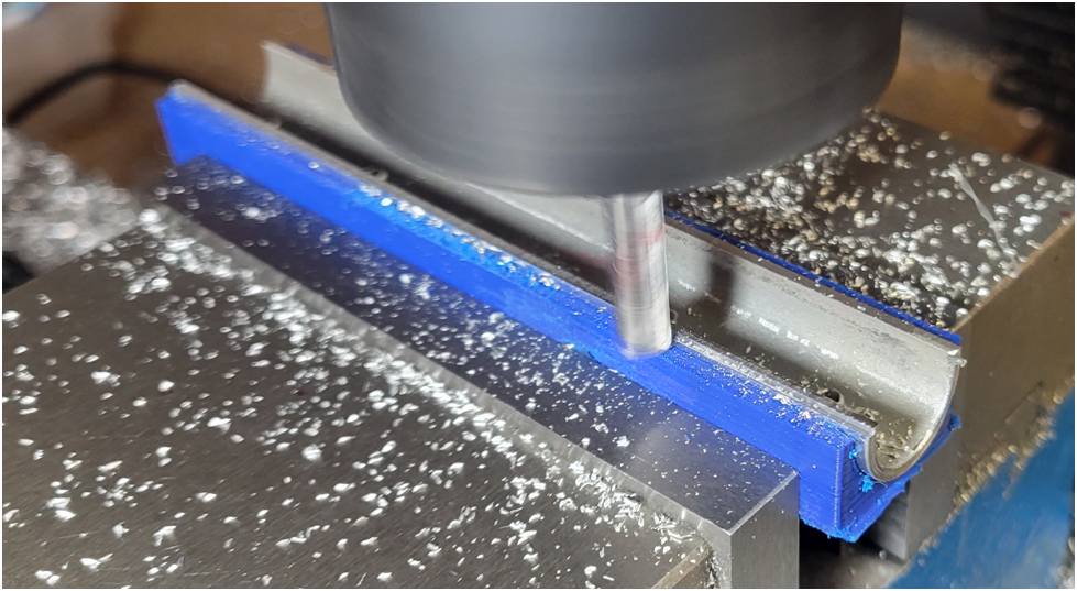
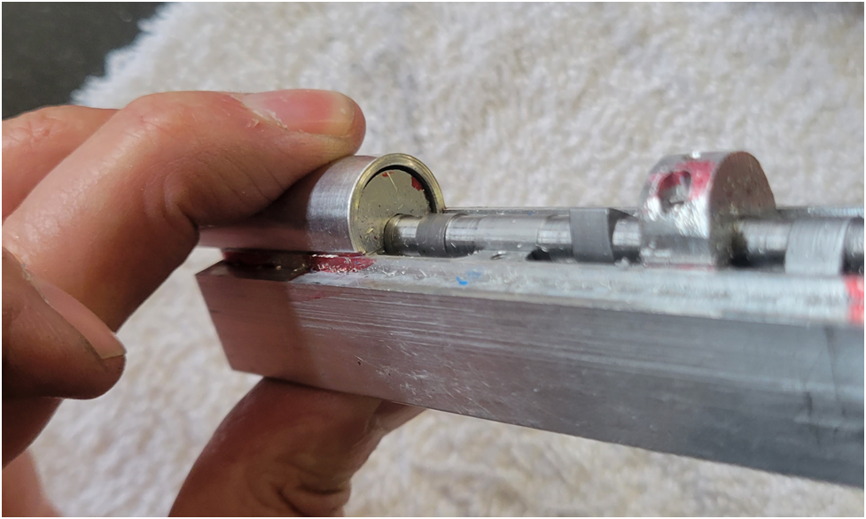
Then, using the mill vise, I press the male form tool into the split tubing.
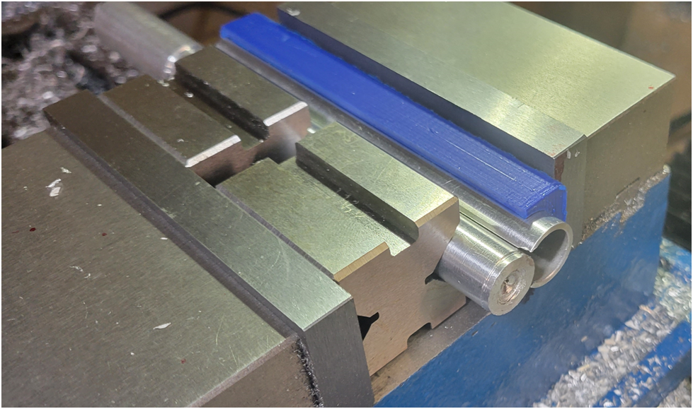
The tubing section is more than a 1/2 section, so the male form tool pops into place.
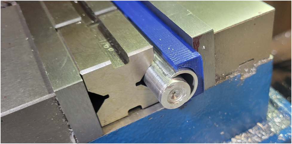
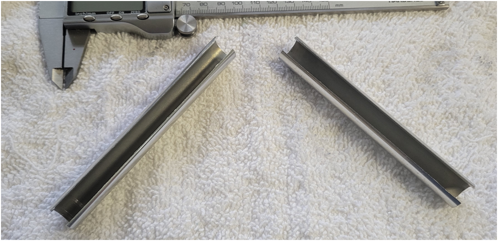
Below is the split tubing now sprung to the male form tool.
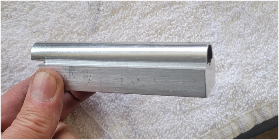
I press the male form tool free of the tubing section and now have my .67″ diameter tube section.
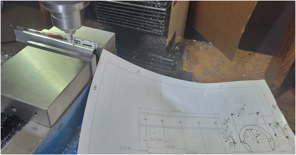
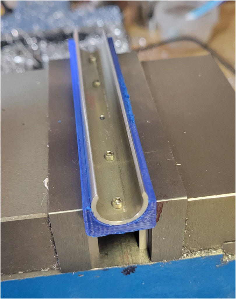
Next I drill the 5 holes that will be used to mount the cambox cover to the cambox.
Below the holes are cleaned up.
Then the tube sections are screwed to the female form tool which will be used as a holding fixture.
This is clamped in the mill vise on parallels. The fixture will orient the work piece so the holes will be in the top center of the finished cambox cover.
The bottom of the cambox cover is machined to set the total height of the cover.
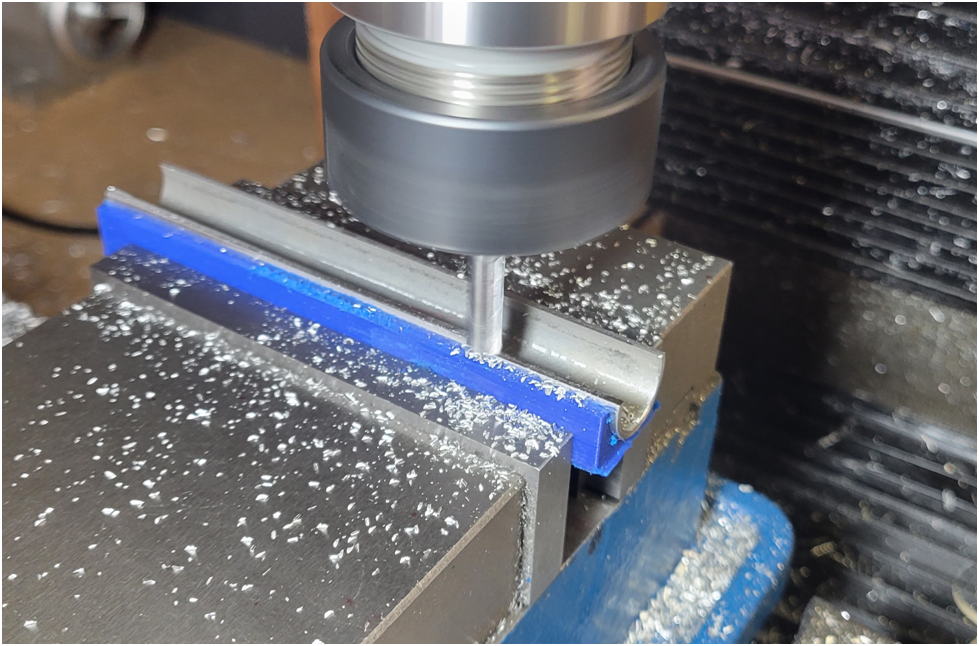
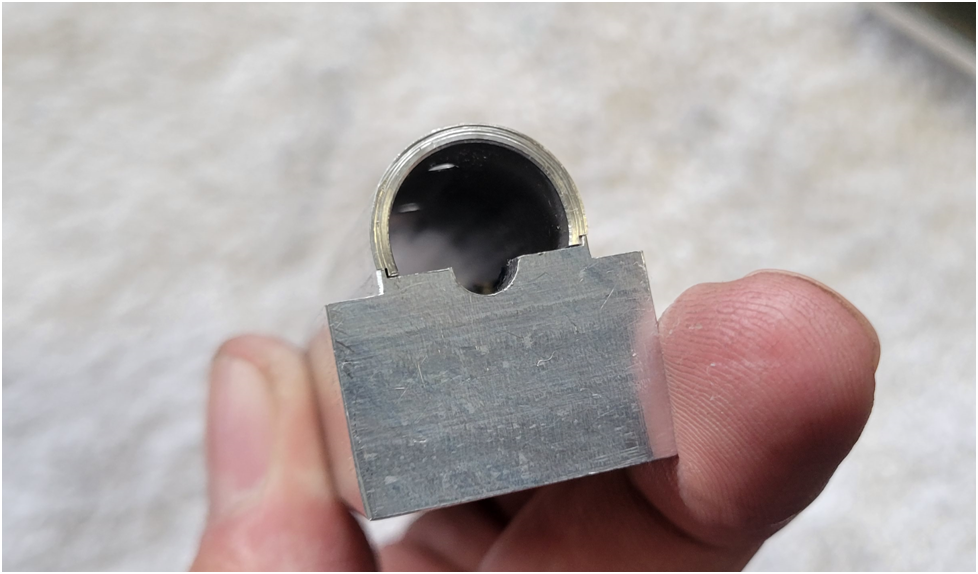
Then a notch is machined into the bottom of the cambox cover so it fits tightly to the cambox.
Below is a finished cambox cover snapped in place on top of a cambox.
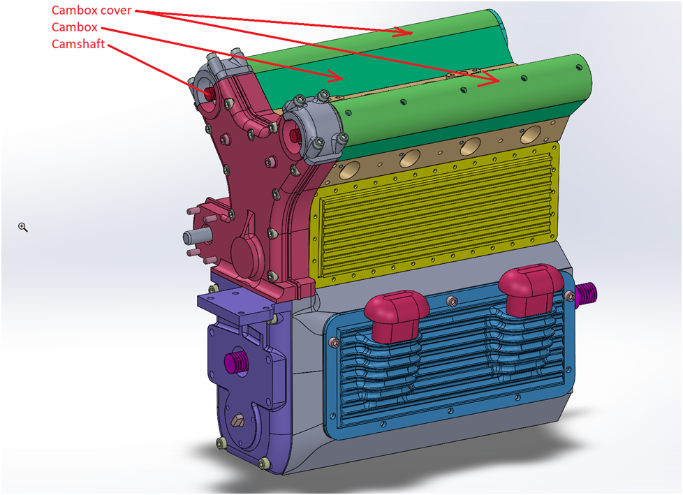
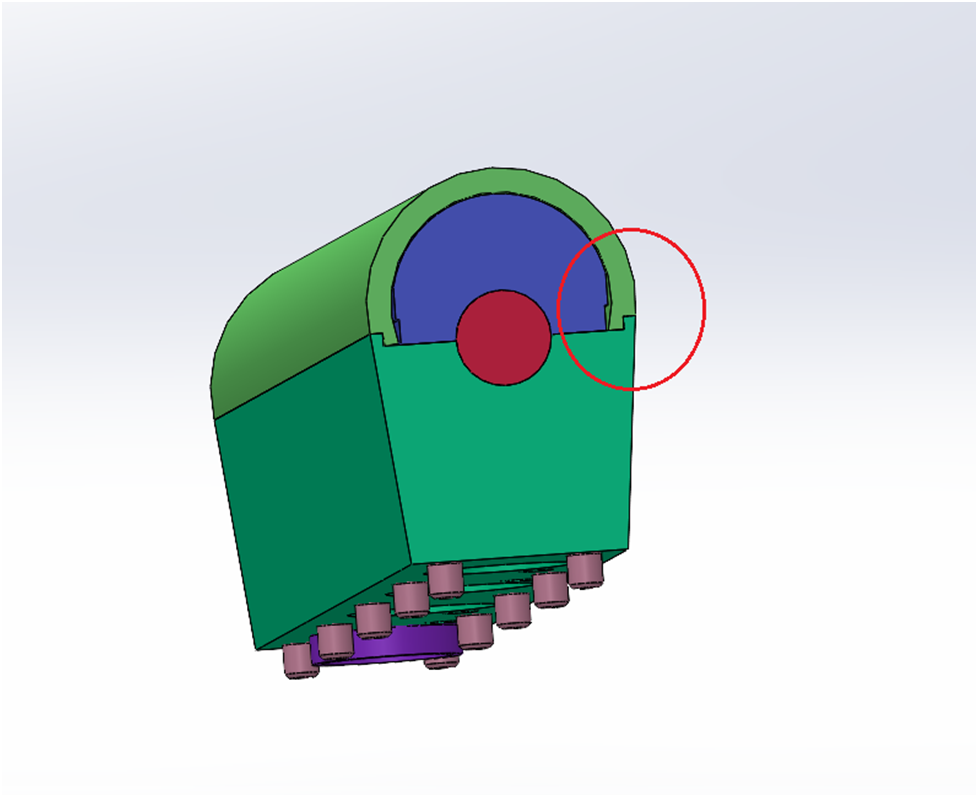
The 3D model showing the notch feature of the cambox cover:
And a closeup of the finished cambox cover mounted on top of the cambox. Note that only the top machining has been competed on the cambox.
Below the cambox cover is in place and shows the clearance between itself and the camshaft bearings which double as attachment points for the cam cover screws.
And finally the finished cambox covers.