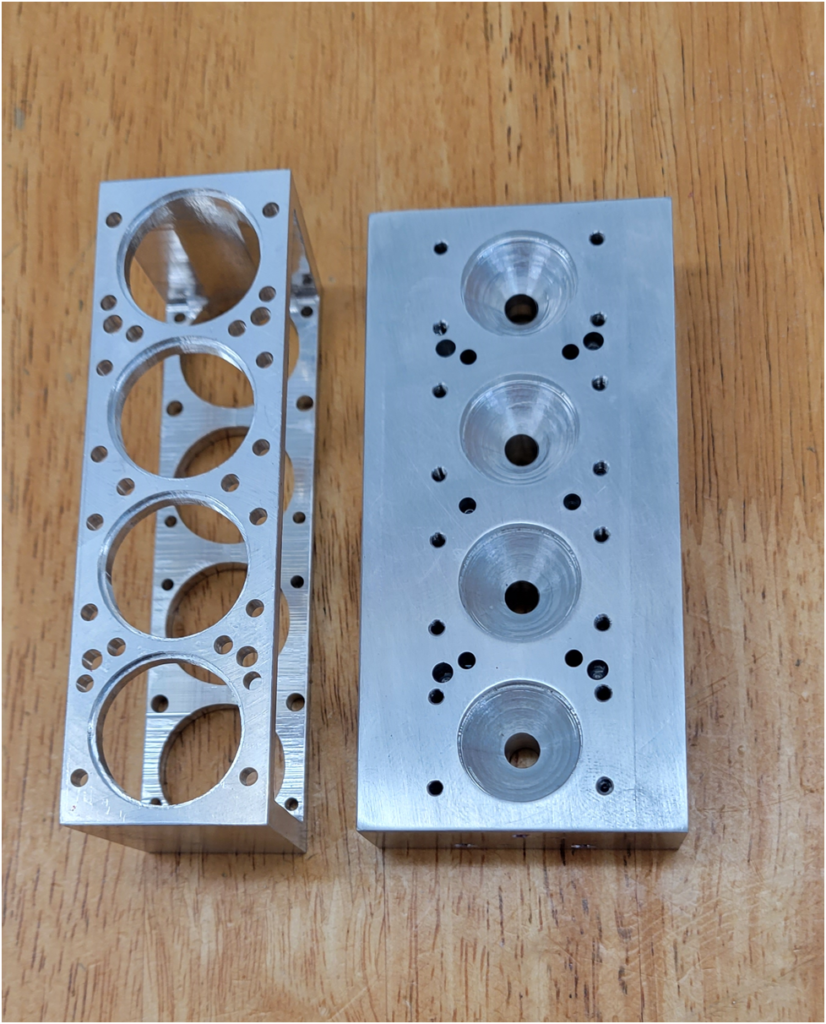
The cylinder head is one of the most complex parts in the engine. It has coolant passages, oil passages, not to mention the intake and exhaust ports. The camboxes mount to the head and so its dimensions dictate how well the timing gears mesh.
I start with machining the internal features including the coolant passages and the coolant cavities. The coolant passages connect the coolant water pipe flanges with the internal coolant cavities. The coolant passages are drilled the long way through the head, they are .150″ in diameter, so drilling the 2″ from both ends to meet in the middle is relatively easy.
The coolant cavities are machined into the head with a 1/4″ roughing end mill.
Three small matching cavities covers are made from 1/8″ aluminum sheet.
The caps are secured in place with high temperature structural adhesive.
I set the adhesive aside to cure for a day and then fly cut the head top to final dimension.
I am happy with the way the sealed coolant cavities turned out. No one will know about them but us.
I drill the four spark plug holes.
Then I begin machining the bottom of the head.
Once the conical combustion changers are machined on the CNC router, it is back to the manual mill to spot drill, drill and tap the holes on the bottom side of the head.
The holes match up nicely with the mating ones in the cylinder block.

Then the head is flipped on its side and the intake and exhaust ports are drilled.

Then back to the CNC Router to machine the features on the top of the head, the water flanges and spark plug wells.

Below are a couple of pictures of the squared head with the features machined on all sides.

Can you see where the internal coolant cavities were sealed with the coolant covers?

But the fun has only just begun. I need to machine four facets into the head for the camboxes and the intake/exhaust manifolds. Before I can move forward on these I need to machine some fixtures to hold the head so I can machine off the corners. Remember, it is supposed to look like this:

Stay tuned for part 2…….