The Offy has two overhead camshafts, here I will machine the exhaust cam shaft. The intake camshaft will follow the same process, but with a different cam lobe profile.

Cam Blank diameter .430″
Cam Base Circle Diameter .25″
Nose Radius .025″
Lift .090″
Flank Diameter . 743″
Lift Duration 128 degrees
Max Lift Occurs: 235 degrees after TDC
I start with a 5″ length of 7/16″ drill rod and drill a 1/16th inch hole all the way through for the oil feed. I drill from both ends and meet in the center. I start with a shorter drill bit and peck drill, drill a crank or two on the tail stock, retract, clear the chips and repeat. I then use a longer drill bit as shown below. I do not drive the drill bit; it is a very light touch where I am letting the drill do the work and I take up the slack with the tail stock handle.

Then I machine a flat on the cam shaft blank, This is used to register the lobes.

Below I use a level sitting on the flat to establish a zero degrees on the rotary A axis.

Then I machine one lobe at a time, sticking out as little as possible for each lobe.
The flat can be seen below.

And the lobe taking shape is below:

When machining of the lobe is complete, I pull a length of stock from the collet, reestablish the zero point on the rotary axis, then turn to the rotary position of the next lobe, reset the zero point on the rotary axis. And run the lobe cutting program again.

Below is the camshaft blank with the four exhaust lobes machined.

Then we move over to the lathe and turn the rest of the features.

Below is the print and dimensions used for first section of the cam shaft.

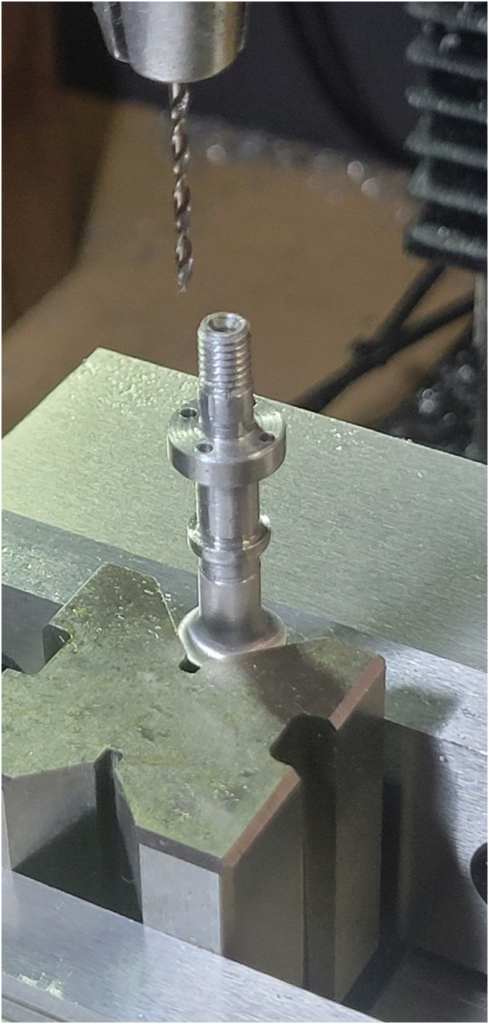
Below I am drilling four holes in the cam shaft that will be used to register the cam gear. With a similar set of holes in the camshaft gear I will be able to adjust the cam timing.

Then I proceed to turn the remaining bearing surfaces on the cam shaft.

Below is the camshaft nearing completion. It still requires some polishing of the bearing surfaces and cam lobes.
