I am going to try something different with the connecting rods. I want to install a bronze split bushing in the big end. It will be secured with Loctite and bass taper pins. As a warning, my first attempt was a failure as can see below:

The bushing is too thin and the material is very brittle and hard to machine. I want the cap screw holes to clear the bushing, but the distances are really tight and the resulting bushing is too thin.
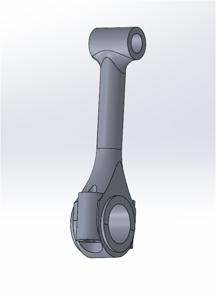
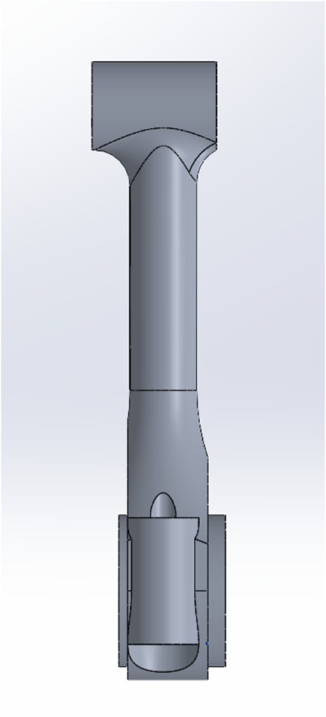
To back up a bit, the following images are of the desired connecting rod. It is not symmetrical as can seen in the side view due to the geometry of the crankshaft with respect to the pistons–the big end is offset from the piston center.


Below is the material squared up and ready to go, fortunately I only make one to start with.

I drill a clearance hole in the work piece to facilitate CNC machining.

Then I turn the bronze bushing to size.

The big end profile is machined:

The hole is reamed and the bronze bushing is installed with Loctite.


The end cap has the cap screws holes drilled/tapped and countersunk.

A slitting saw is used to separate the cap. I use a 1/32″ thick saw blade.

so far, so good.

The surfaces are wet sanded and then the cap is screwed into place.

I then drill and ream out the big end hole. This is where things went awry. Perhaps the drill was not sharp enough, I got too aggressive, or the design was simply poor not allowing enough bearing material.


The gudgeon pin hole was drilled and reamed.

And again the end result:

So I redesigned the Conrod. I moved the cap screws outward to allow for a thicker bearing and I added some material to the con rod cap.

Below is the beginnings of a second try. Here I have completed all of the above steps to the point where I am letting the Locktite cure–that will be over night. The bronze bushing diameter the first time around was .4385″, the second attempt is .499″. The ID will be .375″, so I will have more meat in the bushing, but less in the cap.

I will report back after the rest of the conrod machining is complete.