
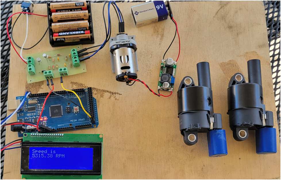
I am working on my electronic ignition for my twin cylinder 4 stroke. Here I am using a DC motor with a magnet mounted on a collar triggering a hall sensor–this simulates the setup on the engine. I will use a magnet mounted to the crank and fire both spark plugs at the same time, ie wasted spark. I will use a little microcontroller to adjust the timing advance from 5 to 25 degrees before top dead center depending on the RPM. The circuit board has the analog circuitry that converts the hall sensor output to a nice 1 millisecond pulse, and then another transistor stage that will drive the coil over plug (COP)s from a signal generated by the microcontroller. The pulse to the COPs will be 4 millisecond in duration. This will diminish if the RPMs get high enough to not exceed a 50% duty cycle on the COP trigger signal.
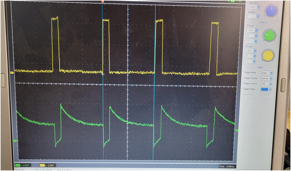
Below is a scope trace of a couple of key signals in the analog circuitry. the green is the signal generated by the RC circuit triggered by the hall sensor, and the yellow is the pulse on the output of the NPN transistor, the RC time constant is set for a 1 millisecond pulse.
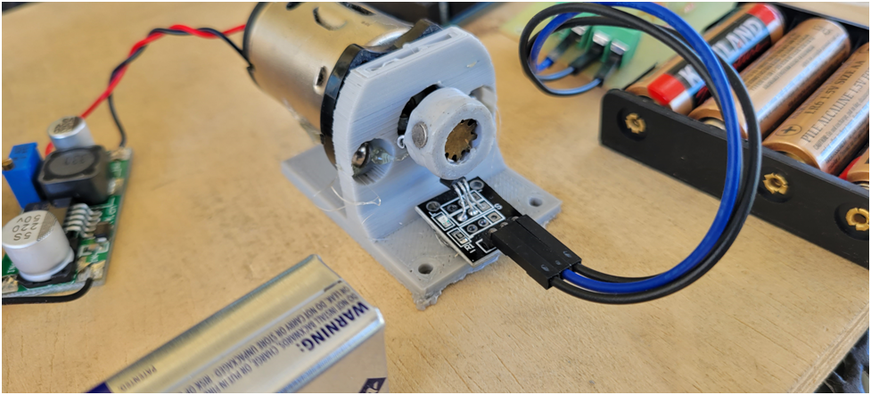
Below is the DC motor setup to simulate the hall sensor on the engine. I can control the motor speed by adjusting the voltage is sees.
Next up is wiring the COPs and the sparkplugs. We will see what EMI havoc is caused by the high voltage travelling through the sparkplug wires.