I have finished installing the rest of the square frames and have laid the keelson. The keelson is three pieces with two scarf joints and a dowel is installed at each frame. Jerry, I am not familiar with the plans you showed. I would be interested in seeing the deck layout for the original bluenose as that is the direction I am goiong now.
I am now modeling the lower deck shelves and lower deck beams. The mast steps are also ready to install.
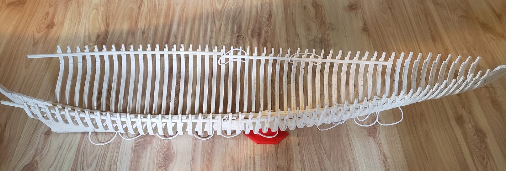
Not much to report other than I continue to install frames to the keel. I have a few half frames abaft to install, then the horn timbers, spiders and the cant frames.
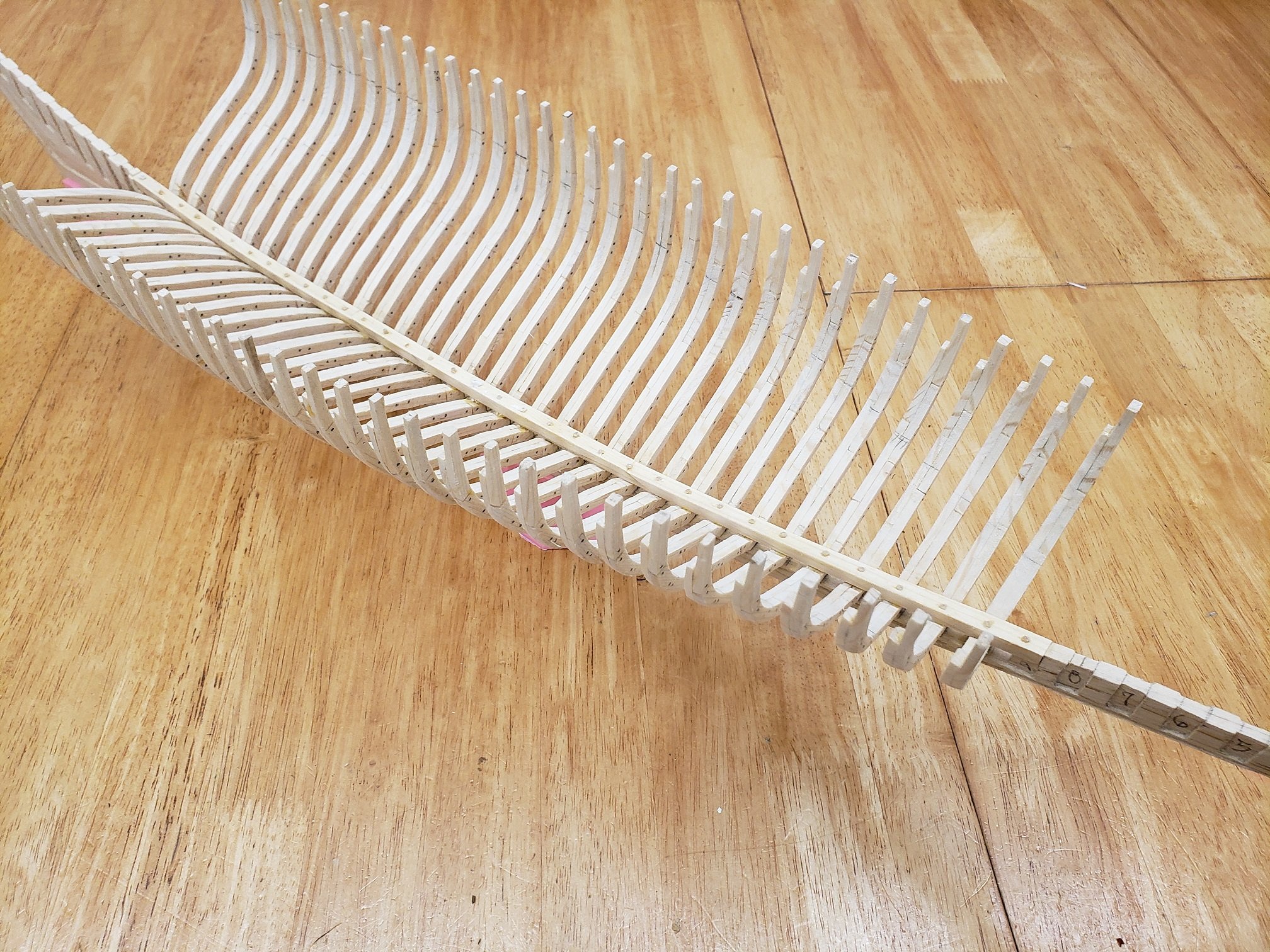
This is an fun view from below the waterline; you can discern the hull shape.
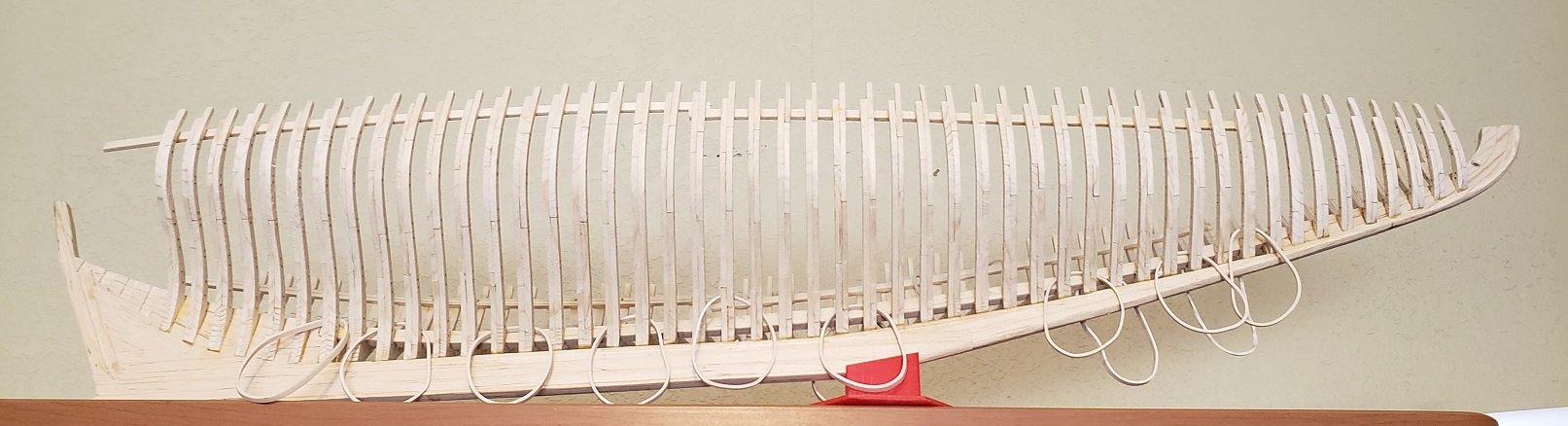
Over the memorial day weekend I completed glueing of all the aft half frames to the deadwood. I still need to drill and install treenails to all of the half frames, fore and aft.

Today I worked on what I call the Horn Timber/Spider leg assembly, the cant frames are bolted (OK, glued) to this. It is not very big but it has some complex shapes.

I made patterns and fabricated it in three parts, the horn timber, and two spiderlegs on each side.
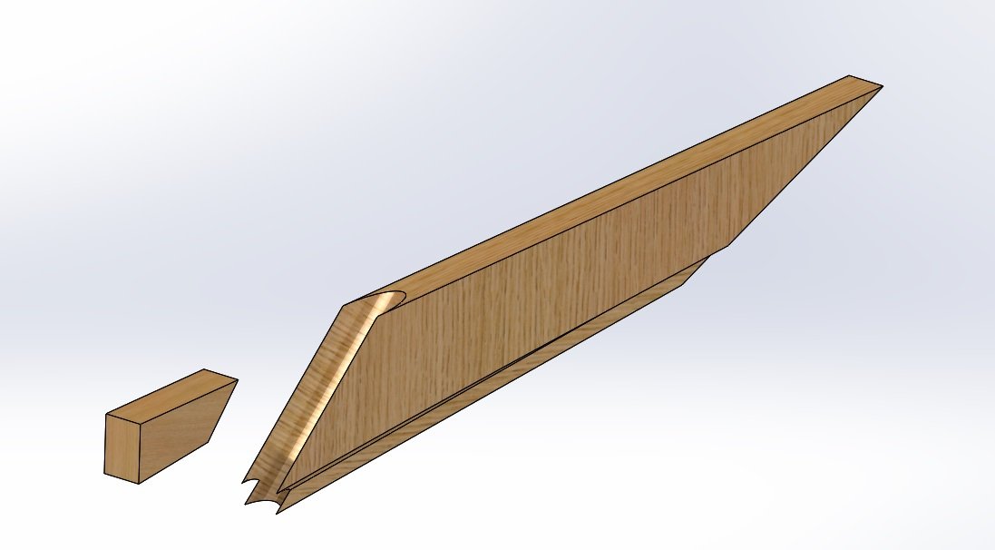
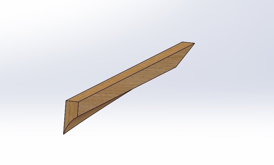
That is the horn timber and below is one of the spider legs
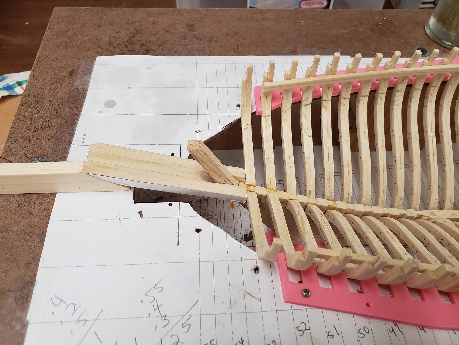
Below the Horn Tiber/ Spiderleg assembly is being test fit in the fixture. You can see the rudder port behind the stern post.
This is the underside:
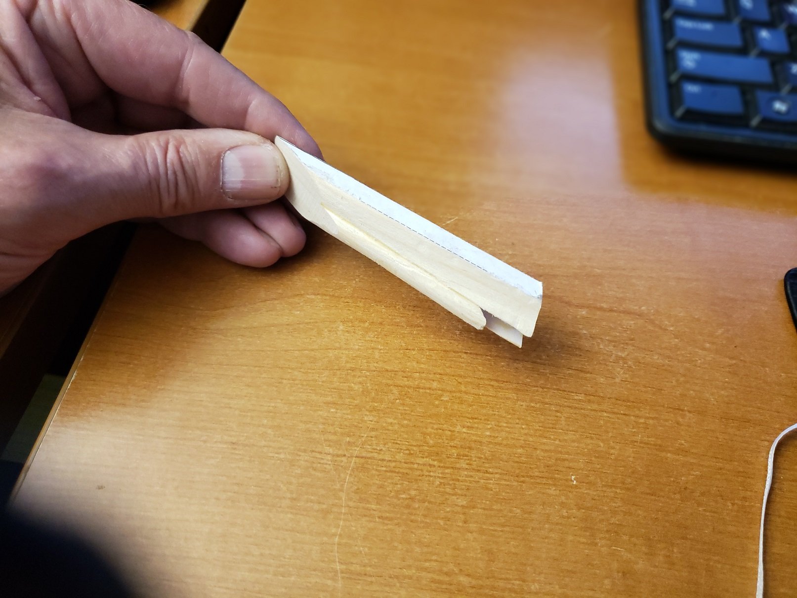
There are five pairs of cant frames that attach to this assembly and, of course, the transom is fixed to the back where my thumb is.
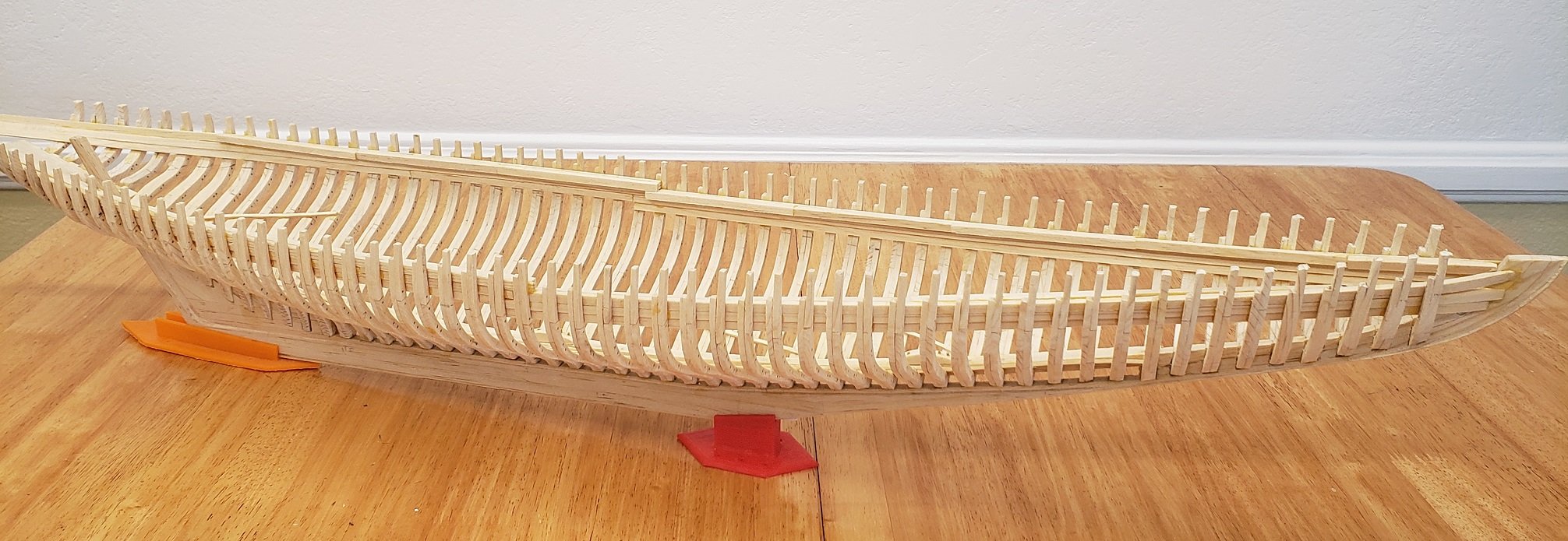
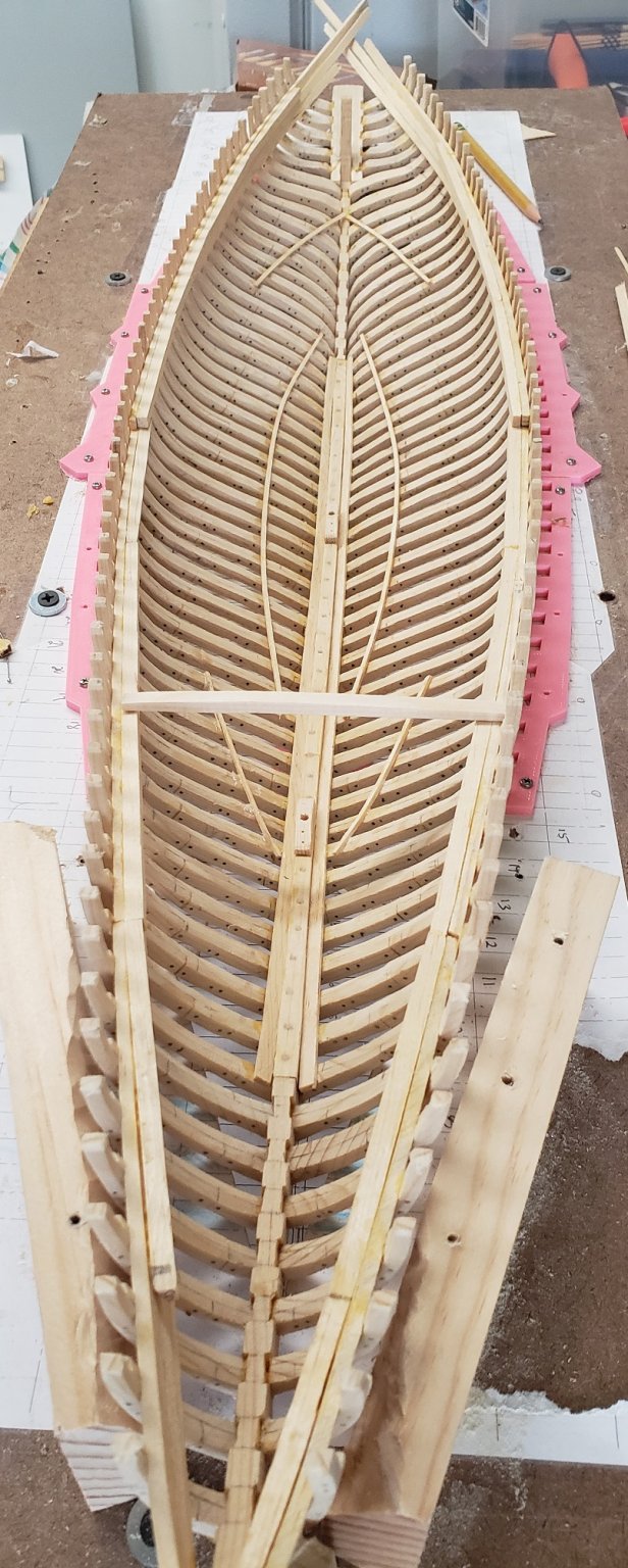
I have installed all of the frames and have been able to breath a sigh of relief, this was a little nerve racking as each frome had to be positioned just right. The fixture worked out really well. Below I am installing the clamps to the frames. “Clamps” are the timbers that tie all the frames together at the deck. Don’t confuse them with my colorful Harbor Freight clamps.

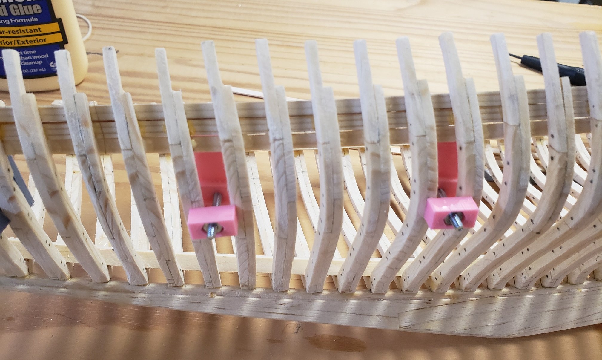
To install the lowest “clamp” I used some custom made 3D printed screw clamps that were designed to fit between the frames
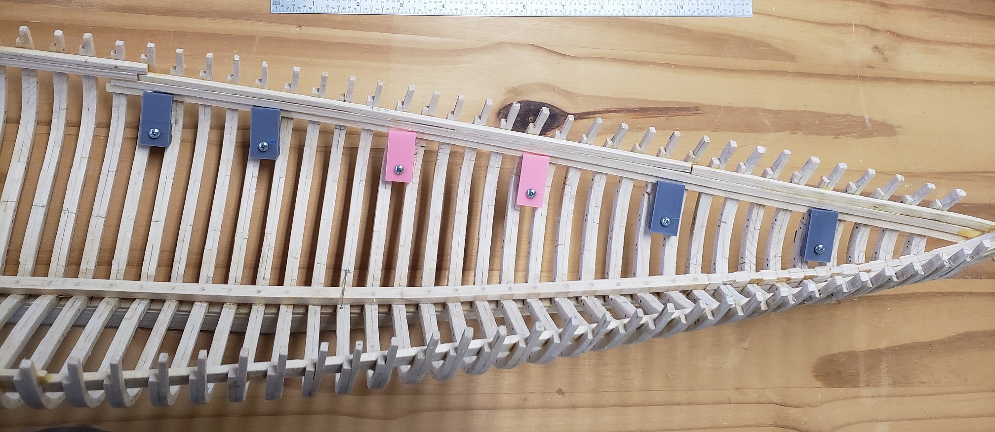
Here is a view from the outside of the frames.
Once the three “clamps” are glued to the top of the frames, the “shelf” is bonded to the top most “clamp”. This shelf then supports the deck beams. Throughout the build I have taken some liberties, but in the case of the shelves I cut them to 4″ lengths as this is 16′ in scale and realistically timber does not come much longer than this. Each shelf piece was sanded on the side that is glued to take on the curve of the hull and to present a level top side for the beams.
Below is what I call the last “picture in the fixture”. See if you can identify: The lower deck shelves , there are three sets, the main cabin, the fish hold and the foc’s’le. How about the mast steps, the sister keelsons, and one lone deck beam.