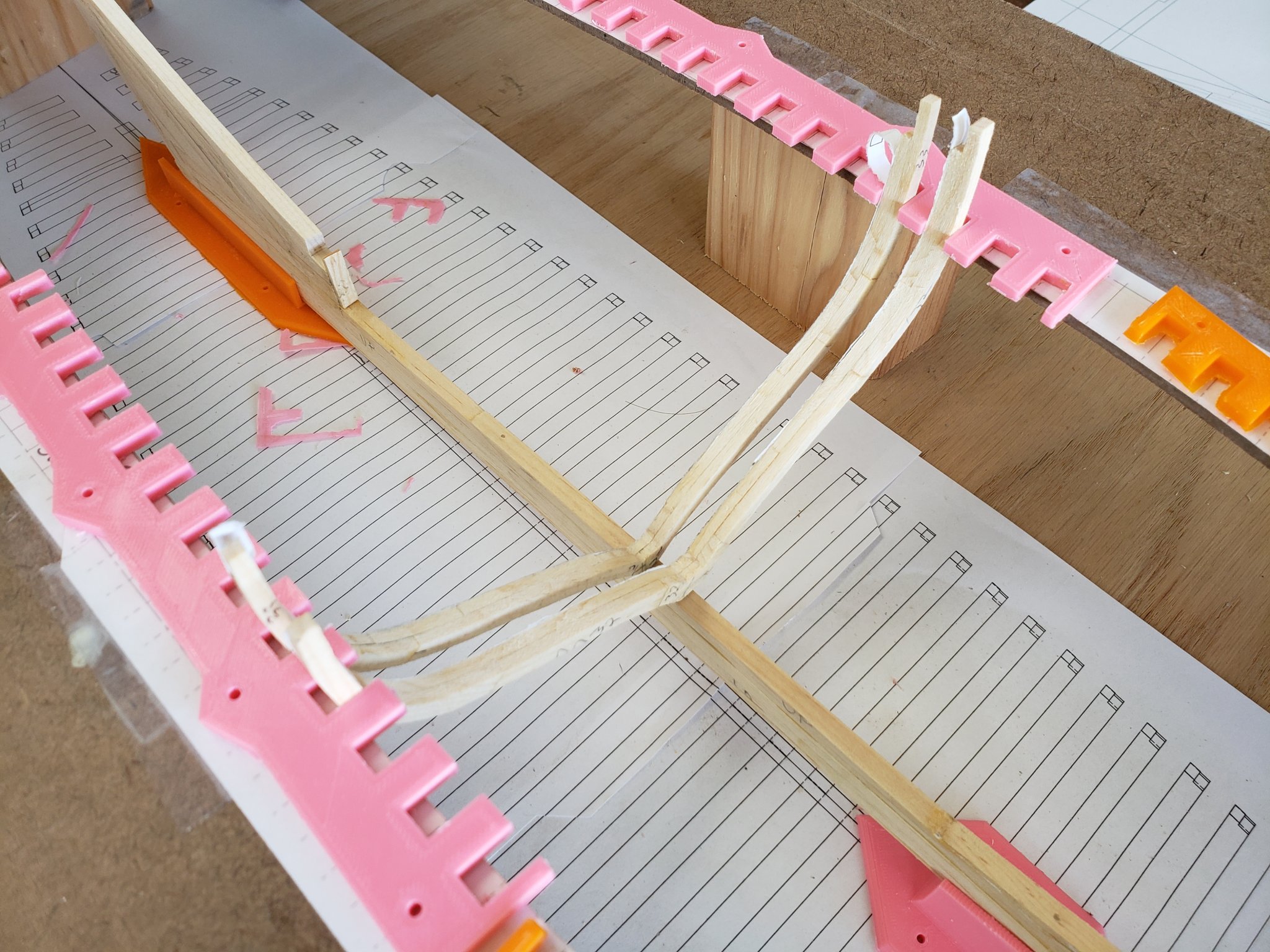
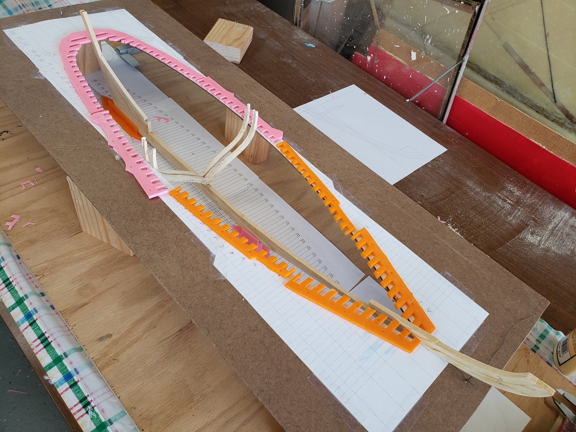
I still have work to do on the keel and frames, but I want to get the framing jig set up and trued. I am using the 3D printer to make the critical alignment fixtures. Parts off the 3D printer are very repeatable and dimensionally accurate. I cut lenghts of 2X4 as stands for the top fixture. I cut them as accurately as I could, but I am still going to need to use a few thin shims out of thin sheet plastic to get the proper spacing between the botton framing jig and the top framing jig.

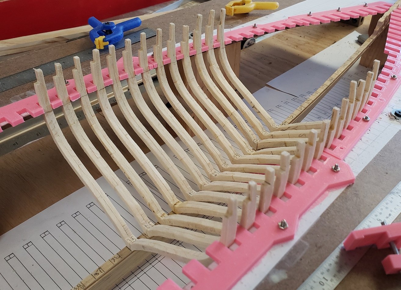
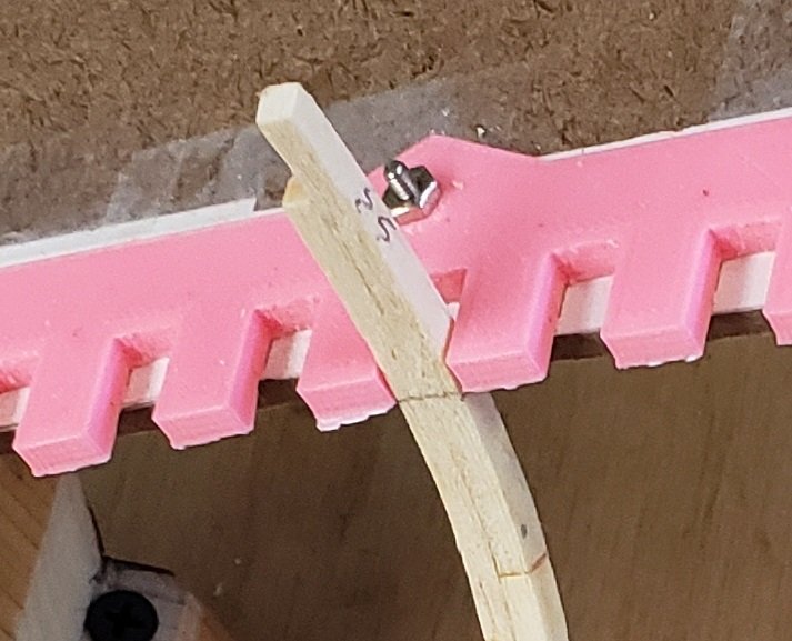
Below I have set acouple of frames into the fixture and found everything lines up very well. The top edge of the top framing jig is right at the waterline and the waterline will be marked on all of the frames. The frames will rest against the top jig and sit on the keel. The keel is supported at two places on the bottom framing jig and two places on the top framing jig.
Major Milestone for me today. I glued and doweled the first frame to the keel. I have spent the greater part of this past week adjusting the framing jig making sure it is perfectly square in all regards. I shimmed and adjusted until everything is locked in to as tight a tolerance as practical.
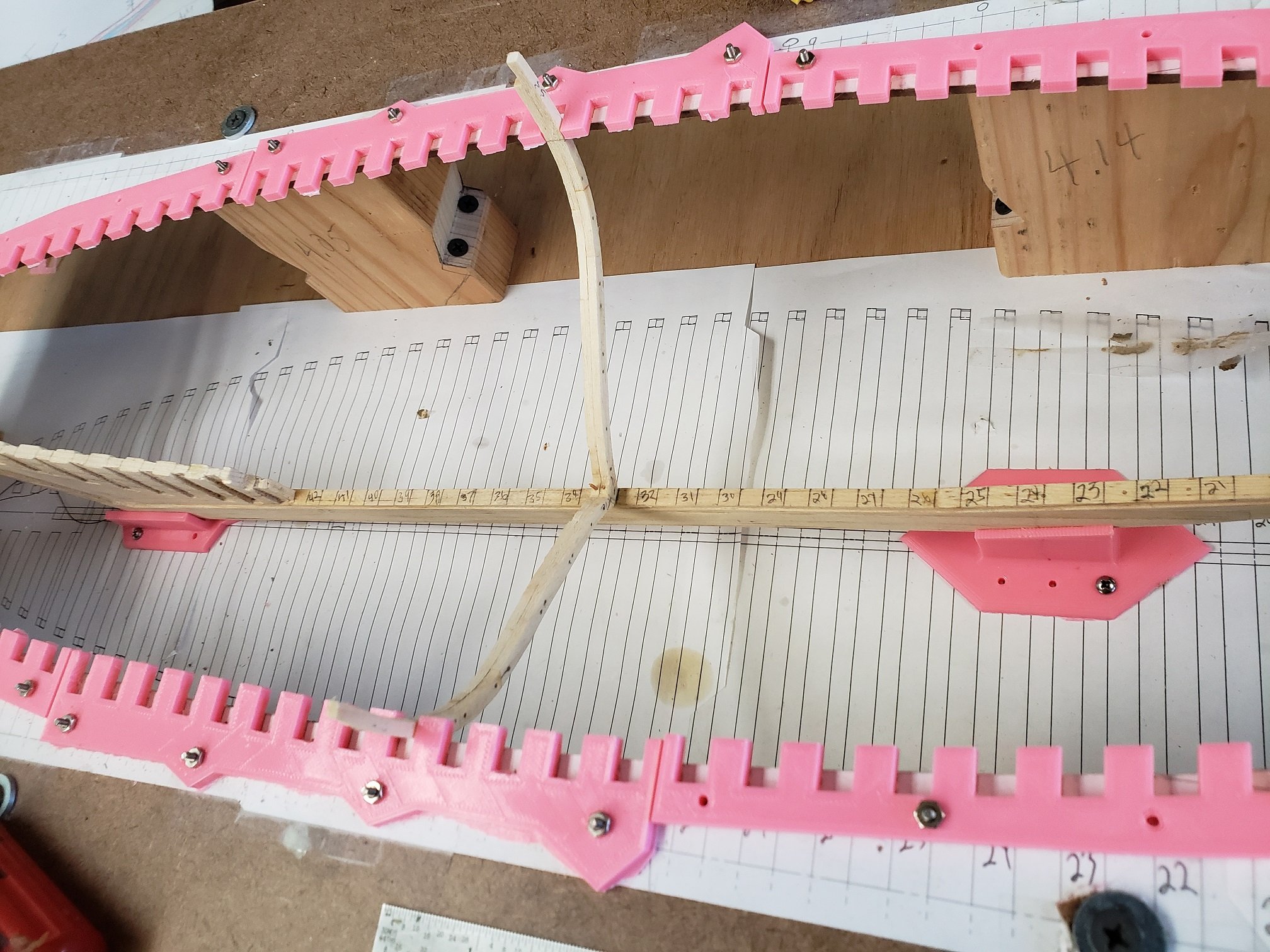
Some details to notice. Each frame is marked with a waterline that is supposed to line up with the top of the top framing jig. The the photo below, It is the light pencil line on the inside of the frame right at the bottom of the pink spacers. The spacers are .15″ thick for reference. One of the dowels securing the futtocks together can be seen. Or, if you want to get technical, securing the stanchion to the 5th futtock :-).
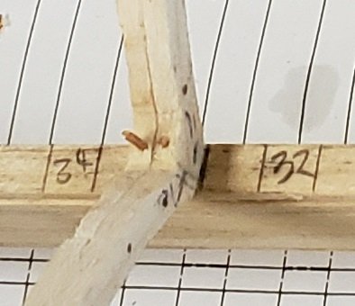
Here is a closeup of the frame to keel attachment. There is no notch in the keel to accept the square frames, but they are glued and doweled. Later the keelson will be laid on top of all the frames., also glued and doweled.
Things I would do differently: I used a stout piece of .75″ cabinet grade plywood for the jig base, but then used masonite for the top piece of the framing jig. The masonite is only .11″ thick and is too flexible. The top sheet should be at least .25″ thick.
The Bluenose will have a total of 58 frames: 5 Cant frames attatching to the spiderlegs/horn timbers, 11 Cant Frames (half frames) attaching to the deadwood of the keel, 9 Cant frames attaching to the Stem, and 33 Sqaure frames sitting on the keel. From the original Bluenose specificatins we know the Frames were a foot wide, spaced at 27″, and held together by Treenails (Trunnels). From a drawing by L. B. Jenson created in 1975 with the assistance of Mr. Fred Rhuland and Mr. John Rhuland, ship builders at Ludenburg, the number of frame types as I have described above can be seen. At my scale of 1:48 this results in frames 1/4″ thick and on 9/16″ centers.
Here I am test fitting more frames. These still need a bit of final shaping and the dowels installed before final attachment to the keel.